Adjustment
Here are Honda's valve adjustment instructions for the C90/CT90 engine.
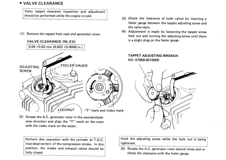
The idea is to set the gap so that the feeler gauge just slides between the tappet adjustment screw and the top of the valve stem.
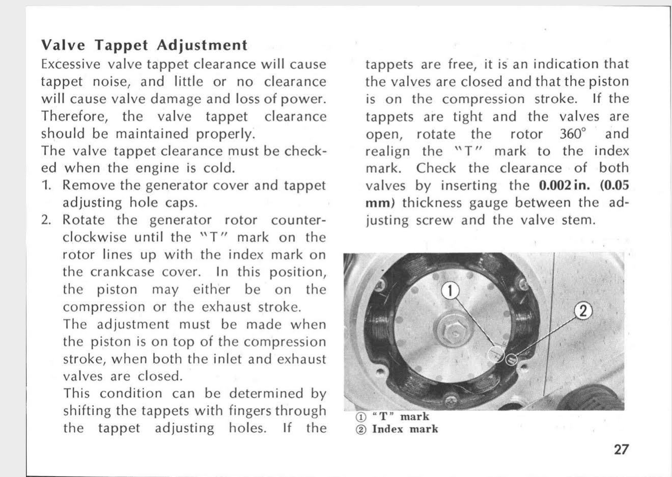
As explained here the adjustment must be done when the engine is cold and when the piston is on top-dead-centre on the compression stroke
Finding TDC on the compression stroke
Honda outlines a convenient way to check the engine is in the right spot:
this method is not foolproof, however, and a reliable alternative is to do the following:
2. rotate the generator rotor anticlockwise until the intake valve opens
3. continue to rotate the rotor until the next TDC
To understand these instructions, recall the basic operation of a 4 stroke engine: the piston rises and falls twice in order to complete a full cycle where fuel and air is drawn into the cylinder, compressed, ignited and the resulting gases expelled from the engine:
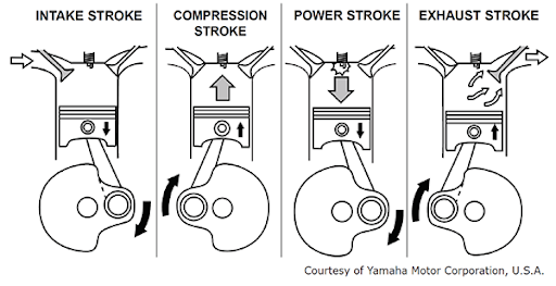
On the first stroke the intake valve opens and the piston descends creating an area of low pressure that draws in fuel/air mixture from the carburettor into the cylinder. As the piston ascends the intake valve closes, sealing the cylinder and causing the mixture to be compressed. The mixture is then ignited by a spark from the spark plug and the expanding gases force the piston downwards.
Finally, on the fourth stroke, as the piston ascends the exhaust valve opens and the gases are expelled.
This excellent film of an engine converted to use a perspex cylinder lets you see this process in action:
It is now easier to understand Honda’s instructions: the ‘T’ marked on the alternator rotor by the factory, when aligned with the pointer on the crankcase, shows that the piston is at the top of its stroke (the “T” stands for top dead centre).
But as we have seen above the piston is at the top of the cylinder twice for each cycle of the engine, so another step is needed to confirm that we are on the compression stroke, which is to say, when both valves are closed. At this point the pressure on the tappets for both valves is relieved so you should be able to feel the tiny amount of play between the rocker arm and the valve stem. Although this is a nice simple test it is not foolproof.
Although this is a nice simple test it is not foolproof. What do you do if someone has already over tightened or loosed the tappets so that this test is no longer works? An alternative method is - recalling the suck/squeeze/bang/blow cycle - to rotate the engine (anticlockwise as per the directional arrow on the rotor) while watching the intake valve until it opens. At this point the engine has just sucked in the fuel/air mixture from the carburettor and is about to begin the compression stroke. This means that continuing to rotate the engine until the next top dead centre (TDC) will get you to the right spot.
So the rule is quite simple: before adjusting the tappet valve gap put the engine on the next TDC after the inlet valve closes.
Now we know how to set up the engine before adjusting the valves – keeping in mind this must be done when the engine is cold
Setting the gap
the 1971 C90 manual specifies the gap should be set to 0.05mm, as does every other manual for small Hondas of the era, but for unexplained reasons the CT90 manual mentioned above specifies the gap can be within a range of 0.05mm +/-0.02mm. As it happens some mechanics do prefer to set a slightly larger clearance than the standard 0.05mm, but please note that setting the clearance smaller than the Honda specification can result in serious engine damage, as explained here.
The adjustment screw has a 3mm square head and you can get a specially designed tappet adjusting spanner, like the one in the illustration below, which makes it easier to keep the screw in the right location as you tighten the 9mm lock nut.
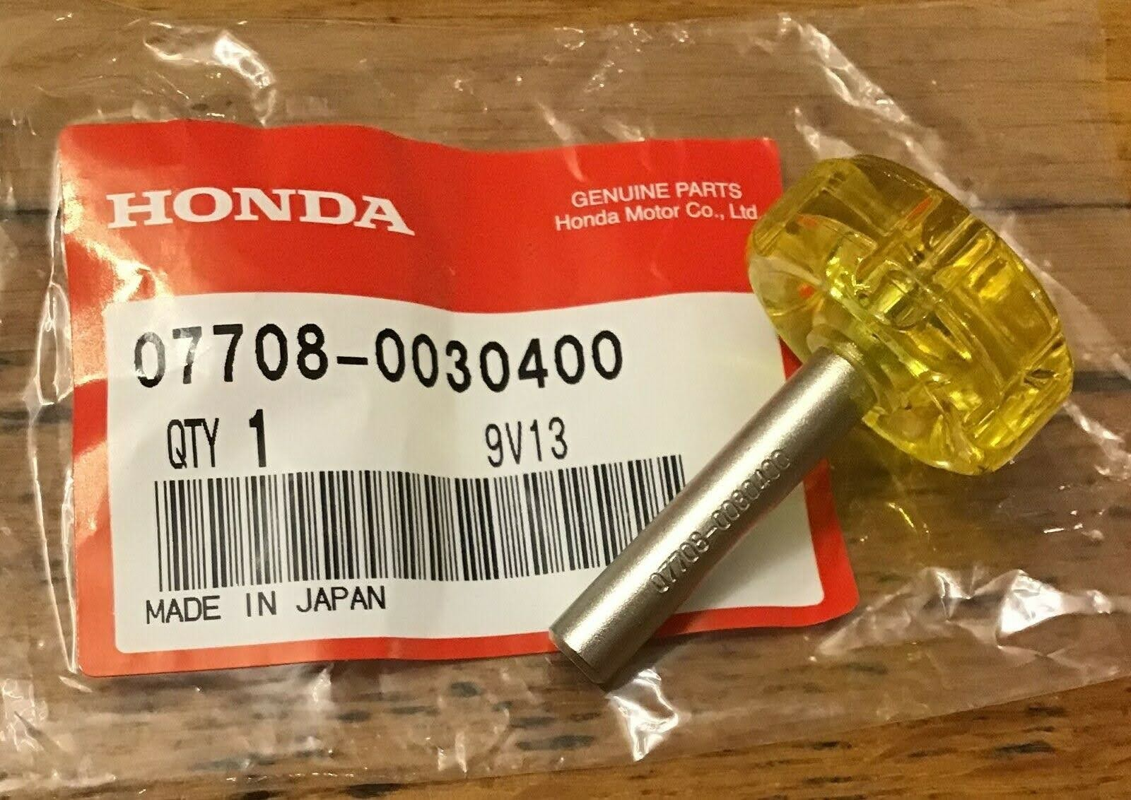
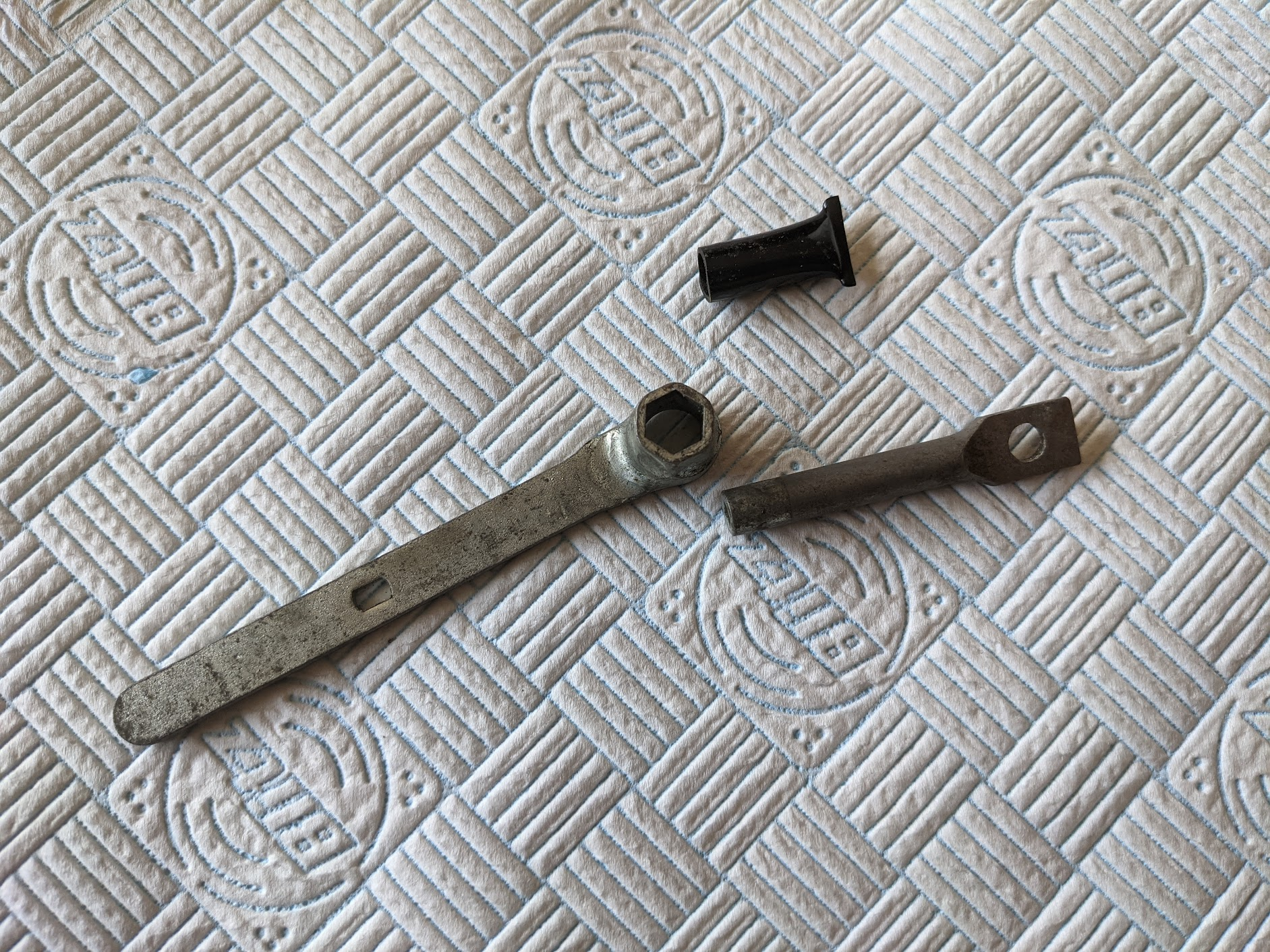
adjusting spanner (left) / The old Kowa tool kits came with something similar (right)
Some people argue that this method for measuring the gap is not completely reliable because over time one or other of the top of the valve stem or the end of the adjustment screw tends to develop a concave depression resulting from the hammering it gets when the engine is running.
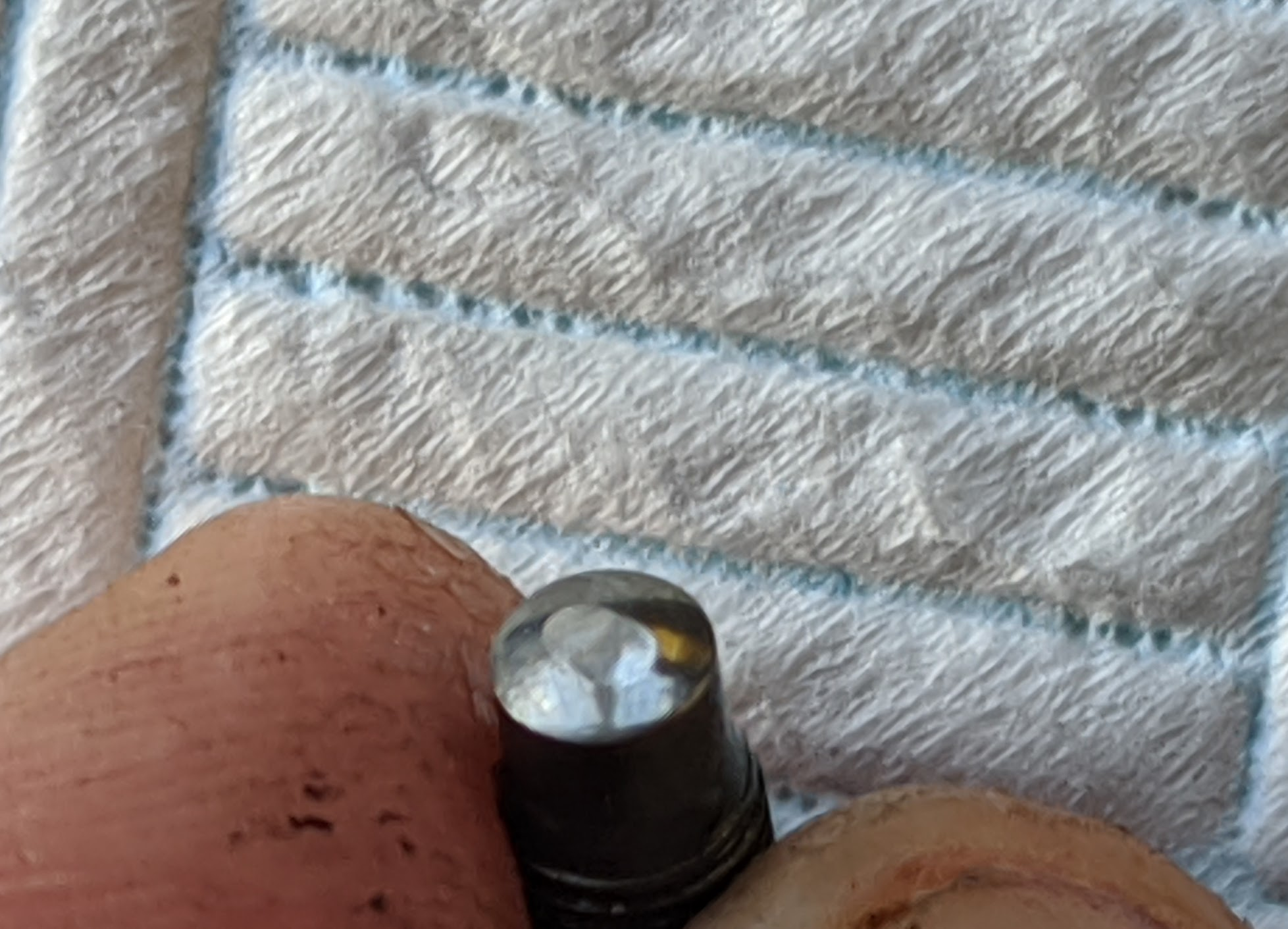
Because the feeler gauge does not conform to the little dent the the actual gap is bigger than the clearance measured and, although the difference this makes must be tiny, so is the gap you are trying to measure.
An alternative method
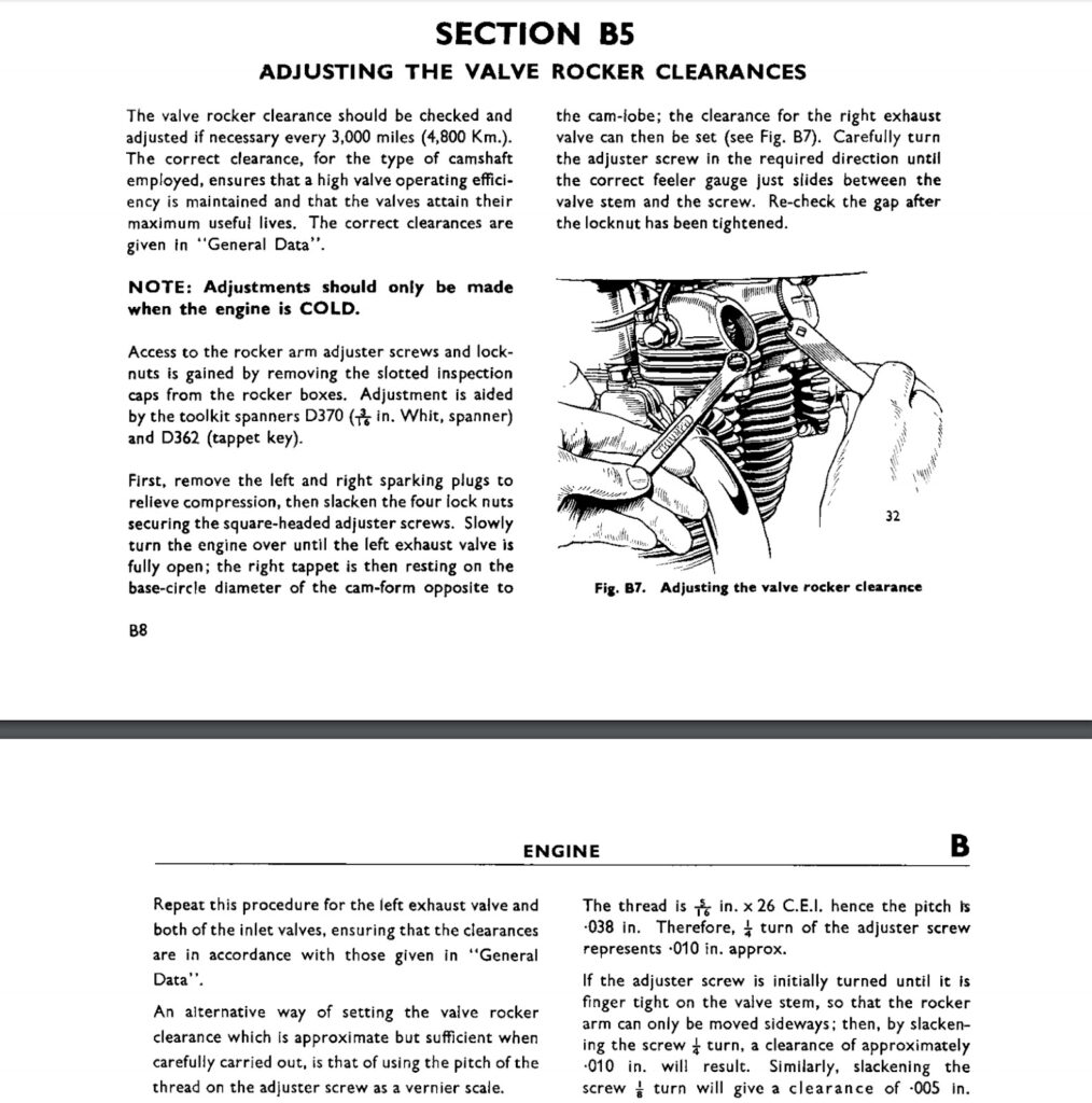
An alternative approach is to use the pitch of the thread on the adjuster screw as a vernier scale. This method is not advertised by Honda, but was described in old Triumph owners manuals like this one:
The thread pitch is the distance between the threads (measured along the length of the fastener) and the pitch of the Honda adjuster screw is 0.5mm:
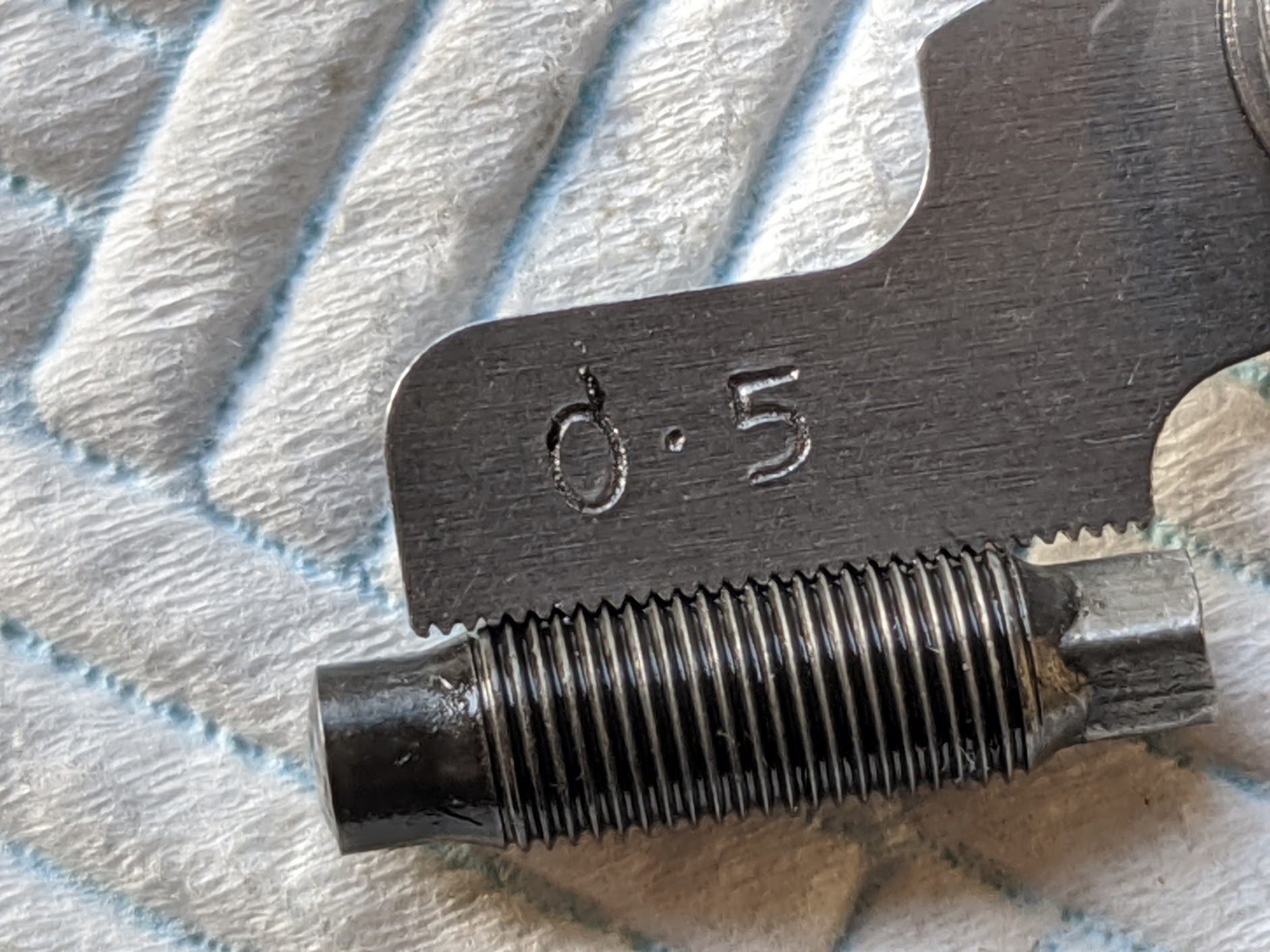
In other words one complete turn moves the screw 0.5 mm. Therefore if you tighten the adjuster screw until is lightly seated and then turn it out ⅛ of a turn the resulting gap will be 0.06mm. This is close to the expected 0.05mm setting and in the range allowed in the CT90 manual. Of course this method is only as reliable as your ability to correctly judge the degree the screw turns and will also be impacted by any lash in the screw threads, which is presumably why Triumph describe it as “approximate”.
Factory Manuals
You don't need to rely on random internet posts like this one to maintain your vintage Honda motorcycle, if you would like definitive instructions it is always best to refer directly to the original Honda workshop manuals. I have uploaded my scanned manuals for reference.